Cisco Catalyst 9200CX Architecture White Paper
Available Languages
Bias-Free Language
The documentation set for this product strives to use bias-free language. For the purposes of this documentation set, bias-free is defined as language that does not imply discrimination based on age, disability, gender, racial identity, ethnic identity, sexual orientation, socioeconomic status, and intersectionality. Exceptions may be present in the documentation due to language that is hardcoded in the user interfaces of the product software, language used based on RFP documentation, or language that is used by a referenced third-party product. Learn more about how Cisco is using Inclusive Language.
Enterprise campus networks are undergoing profound changes to support ever-increasing bandwidth demands on the access layer, heightened by the introduction of 802.11ac and Wi-Fi 6 and the rapid growth of powerful endpoints requiring speeds from 10 Mbps to 10 Gbps. Furthermore, enterprises want access layer switches that can be used in environments where noise is not suitable and space is constrained (such as in retail environments where customers are present, in hospitality environments, etc.) These networking environments are in dire need of an infrastructure that can scale rapidly and accommodate the new breed of endpoints without the need to replace the complete cabling infrastructure.
The Cisco® Catalyst® 9200CX compact switches are the foundation of Cisco’s next generation of compact, enterprise-class, access layer solutions. With the same rich feature set as the other models in the Catalyst® 9200 series, these fanless switches are sold in various configurations, including data-only, Power over Ethernet Plus (PoE+), and 802.3bt Type 3 Class 6 60W UPOE models. They deliver exceptional table scales (MAC/route/ACL) and buffering capabilities for enterprise applications. The Catalyst 9200CX platform delivers up to 128 Gbps of switching capacity, with up to 95 Mpps of forwarding performance. The switches provide nonblocking 1 Gigabit Ethernet (1G) speeds (10/100 Mbps to 1 Gbps) over PoE+ capable copper ports, and nonblocking multigigabit (mGig) speeds (10/100 Mbps to 1GB/2.5GB/5GB/10GB) over 802.3bt Type 3 Class 6 60W UPOE copper ports. These models offer uplink options that support nonblocking 10G Small Form-Factor Pluggable (SFP+) and 1G SFP to meet diverse campus needs when connecting to aggregation or core devices. Additionally, in terms of the power supply options, there are AC and HVDC power supply options.
This white paper provides an architectural overview of the Catalyst 9200CX chassis, including system design, power, and cooling.
The Cisco Catalyst 9200CX models consist of fixed-configuration switches with heat dissipating to the top, going to the switch’s built-in heat sink. They are based on the Cisco Unified Access® Data Plane 2.0 mini (UADP) architecture, which not only protects your investment because of flexible and programmable pipelines but also allows a larger scale and higher throughput. The platform runs on the open Cisco IOS® XE Lite operating system, which supports model-driven programmability, robust security, and flexible visibility.
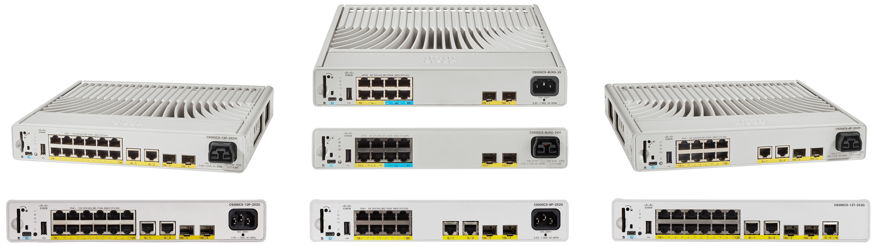
Cisco Catalyst 9200CX switches
The Catalyst 9200CX switches include the models listed below, with variable port speeds and densities to meet the ever-increasing performance demands of enterprise campus environments and provide an architectural foundation for next-generation hardware features and scalability.
1G switches – Catalyst 9200CX fixed uplink models
Data-only switch (with one UADP 2.0 mini ASIC)
C9200CX-12T-2X2G: 12x 10M/100M/1G Ethernet ports with fixed 2x SFP+ and 2x 1G uplink ports and 1x 1G copper uplink PD 802.3bt Class 6.
PoE+ switches (with one UADP 2.0 mini ASIC) [AC and HVDC]
C9200CX-12P-2X2G [AC model] and C9200CX-12P-2XGH [HVDC model]: 12x 10M/100M/1G Ethernet ports with fixed 2x SFP+ and 2x 1G uplink ports. Maximum PoE budget is 240W.
C9200CX-8P-2X2G [AC model] and C9200CX-8P-2XGH [HVDC model]: 8x 10M/100M/1G Ethernet ports with fixed 2x SFP+ and 2x 1G uplink ports. Maximum PoE budget is 240W.
Multigigabit Ethernet switch with 802.3bt Type 3 Class 6 UPOE 60W (with one UADP 2.0 mini ASIC) [AC and HVDC]
C9200CX-8UXG-2X [AC model] and C9200CX-8UXG-2XH [HVDC model]: 4x 10M/100M/1G + 4x 10M/100M/1G/2.5G/5G/10G Ethernet ports (802.3bt Type 3 Class 6 60W all ports) with fixed 2x SFP+ uplink ports. Maximum PoE budget is 240W.
Chassis design
This section briefly covers the high-level system design of the Catalyst 9200CX platform. It is a very simple and flexible architecture.
C9200CX-12P and C9200CX-12T board layout
The Catalyst 9200CX UPOE and PoE+ switches come with one built-in 315W power supply unit that supports AC or HVDC power inputs. The C9200CX-12T (data-only switch) has three different powering options: (1) 80W AC slim power adapter, (2) 80W AC power adapter, and (3) 80W DC power adapter. All Catalyst 9200CX models come with a built-in passive RFID for inventory management, a blue beacon LED for device-level identification, and a tricolor LED for system status.
These switches also have an SD card slot, a USB Type Micro-B console port, and a USB 2.0 port for Bluetooth dongle support. On the side of the switches, a Kensington lock port is present for hardware security purposes.
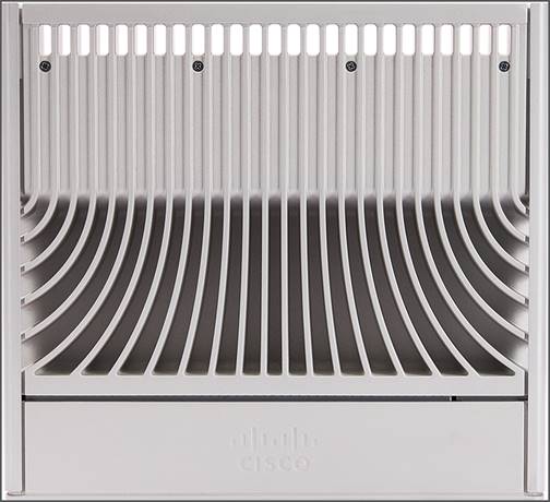
The Catalyst 9200CX switches are fanless and hence noiseless. The unique design of these switches enables them to remain cool even when under stress. The entire top of the switch is essentially a giant heat sink. The unique fin design on the top of the switch enables it to exude heat through the top of the chassis. If the switch fails to meet the temperature requirement, it shuts down automatically to keep the system from overheating.
The Catalyst 9200CX chassis is equipped with an onboard thermal sensor to monitor the ambient temperature at various points and report thermal events to the system in order to maintain system overheating precautions in effect.
C9200CX-12P top view
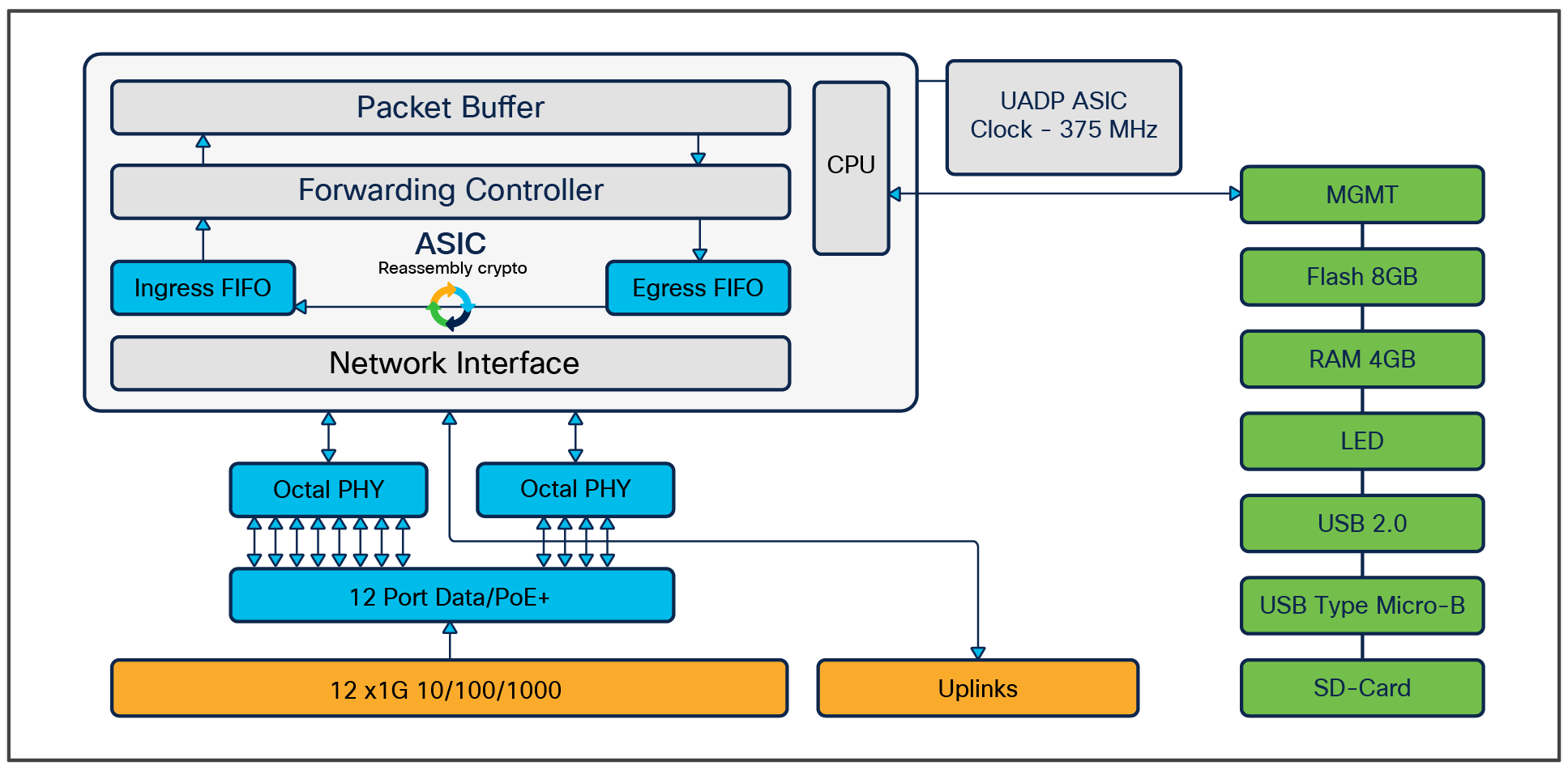
The Catalyst 9200CX switches are line-rate switches that offer configurable system resources to optimize support for specific features, depending on how the switch is used in the network. The switch architecture consists of four main components:
● UADP Application-Specific Integrated Circuit (ASIC)
● Embedded CPU
● ASIC interconnect
● Front-panel interfaces
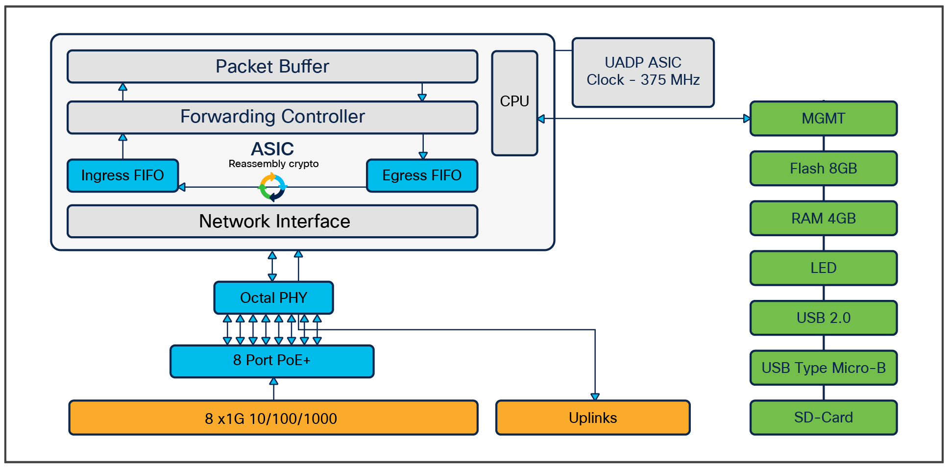
The Catalyst 9200CX is built with the UADP 2.0 mini ASIC, which is based on a System-On-Chip (SOC) architecture. UADP 2.0 is the third generation of the UADP family. It uses 28-nanometer technology and a single core capable of switching 100 GB of data at line rate, and is specifically optimized for next-generation fixed access switches.
UADP 2.0 ASIC block diagram
The architecture and functionality of UADP 2.0 are largely unchanged from previous generations. The key UADP 2.0 capabilities are as follows:
● Packet bandwidth and switching throughput: 100G
● Forwarding performance: 291 Mpps
● Packet buffer: 6 MB
● Dedicated NetFlow block with 16,000/8,000 IPv4/v6
The Catalyst 9200CX switches are equipped with an embedded CPU on the ASIC.
Highlights include:
● 4-core up to 500 MHz embedded ARM
● Single 4 GB of DDR3 RAM
● Flash on RAM: 8 GB
● Support for USB Type A file system (front serviceable) for external storage and Bluetooth dongle
● Support for USB Type Micro-B serial console
● System reset switch for manual power cycle
Ethernet PHY (physical layer) connects a link layer device (often a MAC) to a physical medium such as a transceiver. PHY on the Catalyst 9200CX switches is a fully integrated Ethernet transceiver that supports steering and mapping of lanes back to the ASIC to support multiple speeds (1G, 10G), depending on the optics inserted on the front-panel ports.
Highlights of the C9200CX-12T-2X2G and C9200CX-12P-2X2G/C9200CX-12P-2XGH models are as follows:
● 12x 1G RJ-45 Ethernet ports, all mapped to the single core on a single ASIC.
● C9200CX-12P-2X2G offers PoE+ inline power on all downlink ports for a maximum power budget of 240W.
● C9200CX-12T-2X2G offers data only on all downlink ports. Port GigabitEthernet1/1/5 doubles as a copper uplink and 802.3bt Type 3 Class 6 PD port to fully power the switch.
● All of the uplink ports connect to ASIC0/Core0.
● Port mapping:
◦ All of the ports—1 through 12—are mapped to ASIC0/Core0.

C9200CX-12T-2X2G and C9200CX-12P-2X2G/C9200CX-12P-2XGH high-level block diagram
Highlights of the C9200CX-8P-2X2G/C9200CX-8P-2XGH model are as follows:
● 8x 1G RJ-45 Ethernet ports, all mapped to the single core on a single ASIC.
● All 8 downlink ports offer PoE+ inline power for a maximum power budget of 240W.
● All of the uplink ports connect to ASIC0/Core0.
● Port mapping:
◦ All of the ports—1 through 8—are mapped to ASIC0/Core0.
C9200CX-8P-2X2G/C9200CX-8P-2XGH high-level block diagram
Highlights of the C9200CX-8UXG-2X/C9200CX-8UXG-2XH model are as follows:
● 4x 10MB/100MB/1G and 4x 10MB/100MB/1G/2.5G/5G/10G mGig RJ-45 Ethernet ports, all mapped to the single core on a single ASIC (for 10G, use Category 6a cable or above).
● All 8 downlink ports offer 802.3bt Type 3 Class 6 60W UPOE inline power for a maximum power budget of 240W.
● All of the uplink ports connect to ASIC0/Core0.
● Port mapping:
◦ All of the ports—1 through 8—are mapped to ASIC0/Core0.

C9200CX-8UXG-2X/C9200CX-8UXG-2XH high-level block diagram
This section provides a high-level overview of how packet forwarding is performed on the Catalyst 9200CX switches. Since the UADP ASICs used on all Catalyst 9200 Series models, including the 9200CX models, are architecturally equivalent, single unicast packet walks are described.
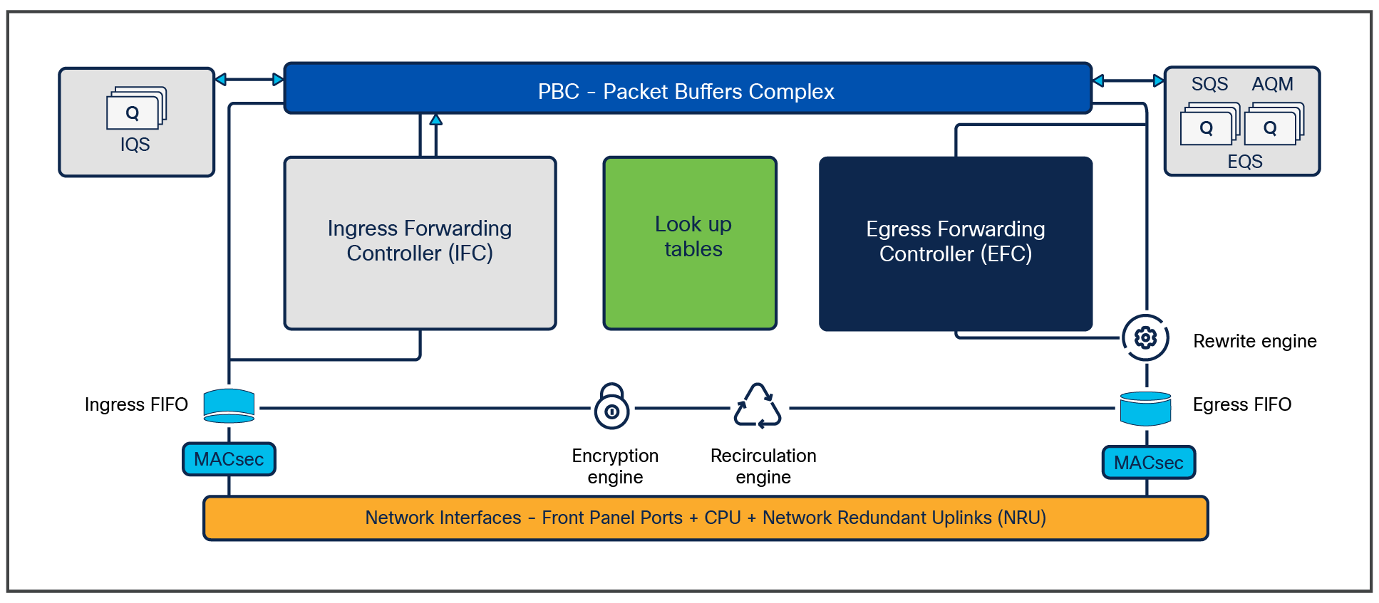
Ingress and egress unicast forwarding within ASIC
The figure below illustrates unicast packet forwarding within the ASIC.
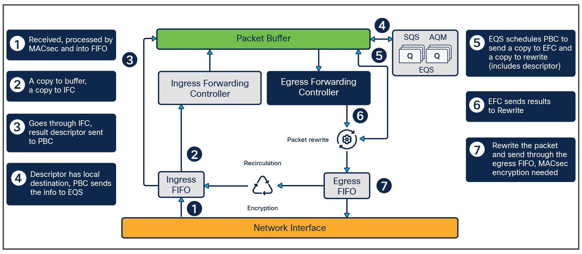
Packet walk within ASIC
The following is the basic sequence of events when packets enter the Catalyst 9200 Series front-panel ports:
1. Packet arrives at ingress port. PHY converts the signal and serializes the bits, and then sends the packet to the Network Interface (NIF) on the ASIC.
2. NIF packages frame into 256-byte chunks and moves them to the ingress MACsec engine. NIF also implements 1588 timestamping and Energy Efficient Ethernet (EEE) if enabled.
3. MACsec engine is a cut-through, fixed-latency cryptography engine to support 802.1AE MAC Security. Core cryptography of Layer 2 Cisco TrustSec® and output frames go to ingress FIFO.
4. Ingress FIFO collects the frames in 256-byte segments and transmits them to the unified Packet Buffer Complex (PBC).
5. Ingress Forwarding Controller (IFC) snoops packets between ingress FIFO and PBC and performs frame processing and a series of table lookups to deliver the resulting frame descriptor to PBC.
6. PBC is the primary packet store on the UADP ASIC. It uses the 64-byte frame descriptor to determine the egress port and QoS treatment of the frame. As the egress port is on the same ASIC, PBC performs local switching by allowing frames to be enqueued directly into egress queues.
7. Egress Queues and Scheduler (EQS) is responsible for queue management, replication, and scheduling packets. EQS enqueues packets arriving from the local ingress path into the egress queue structures and then schedules them for transmission to the corresponding egress ports.
8. PBC receives the packet handle/results from the EQS block and sends the packet to the egress FIFO through the rewrite engine.
9. Egress Forwarding Controller (EFC) snoops the frames as they move from PBC to the rewrite engine.
10. EFC completes egress lookup functions (such as egress Switched Port Analyzer [SPAN] and recirculation) and writes the rewrite descriptor to the rewrite engine.
11. Rewrite engine performs packet rewrite with new descriptor and fragmentation. Packets are rewritten first and then fragmented if necessary and sent to the egress port FIFO. The egress port FIFO provides storage for frames awaiting transmission to either the NIF or the recirculation path.
12. Egress MACsec performs fixed-latency and wire-rate encryption required by the frame for 802.1AE or Layer 2 Cisco TrustSec and then passes the frame on to the NIF in a cut-through manner.
The Catalyst 9200CX switches (with their custom-designed mounting options) were created to be robust while offering unparalleled industry deployment use cases. The use cases are many, and customers have a plethora of options for using these compact switches. Here we’ll focus on four prime use cases.
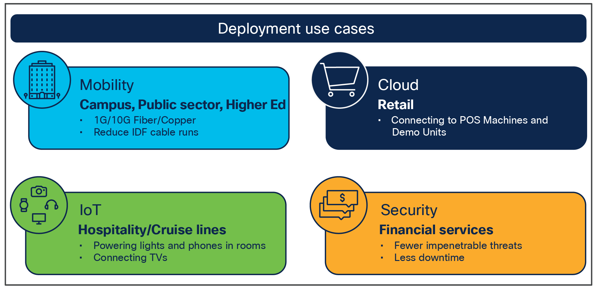
Prime use cases for the Catalyst 9200CX switches
Higher education
Universities are one prime use case where wired access is needed at the dormitory level for students. These 8- and 12-port switches can be used in dormitories to have wired Ethernet connectivity to client devices, and/or can be used to provide data and power to wireless Access Points (APs). Mounting options include ceiling mounting, wall mounting, or desk mounting.
Retail
Retail stores are another prime area where the Catalyst 9200CX switches can add value. From providing data and power to APs to providing Wi-Fi access to customers and providing network connectivity to the various Internet of Things (IoT) devices within the retail environment, these compact switches are indispensable. Mounting options include ceiling mounting, wall mounting, or desk mounting.
Hospitality
Hotels, cruise lines, or any hospitality use case is another prime area where the Catalyst 9200CX switches can be used. For example, they can be used in hotel rooms to provide data and/or power to IP phones, room lights, and other IoT devices. The fanless nature of the Catalyst 9200CX is ideal for environments where people may reside, as they operate noiselessly. Mounting options include ceiling mounting, wall mounting, ground mounting, or desk mounting.
Financial institutions
Banks or any points of contact where currency transactions are conducted are a prime use case for the Catalyst 9200CX switches. These switches enable fast, secure transactions while incurring minimal downtime. Mounting options include ceiling mounting, wall mounting, ground mounting, or desk mounting.
The Cisco Catalyst 9200CX switches are compact, enterprise-class, fanless access switches in the Catalyst 9000 family, offering a comprehensive portfolio and architectural flexibility with 1-Gbps and mGig/10-Gbps downlink ports and 1- and 10-Gbps uplink ports. This new platform is based on Cisco’s next-generation programmable UADP ASIC for increased bandwidth, scale, security, and telemetry. The Catalyst 9200CX platform is built on a flexible architecture designed to provide high performance to meet the evolving needs of highly scalable and growing enterprise networks.
Additional websites that offer more details about the Cisco Catalyst 9200CX switches and their capabilities:
● Cisco Catalyst 9200 Series Switches Data Sheet.
● Cisco Catalyst 9200 Series Switches Hardware Installation Guide.